

How To Draw A Contour Map
six.8.ii Contour Plots and Colour Mapping
Contour-Color-Map
Summary
Origin offers rectangular, polar, and ternary contour plots. For rectangular contour plots, the data tin be either in a matrix or in a worksheet in XYZ format. Polar profile plots tin be generated from iii columns of data in a worksheet, organized either every bit R  Z or R Z. Ternary contour plots can be generated from worksheet data organized in X Y Z Z format where the 2nd Z-column contains the 4th parameter which is the height value at a given XYZ point in the ternary space.
Many options are bachelor for customizing contour plots, such as setting different major and small contour levels, displaying profile lines only at major levels, applying colour palettes, and also control for a custom boundary in the instance of contour plots created straight from the worksheet.
What Y'all Will Learn
This tutorial will show you how to:
- Set values in a Matrix and create a Contour Plot
- Customize levels, lines, and color mapping
- Extract data from profile lines
- Create a Contour Plot directly from XYZ data
- Use a Custom Purlieus
Create Contour Plot from Matrix
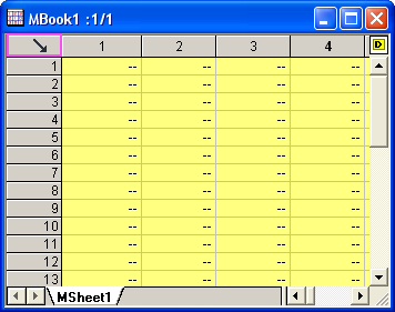
- To create a new matrix click the New Matrix button
 . Motion the cursor to the upper left corner of the matrix until the shape of the pointer changes equally in the following image and click to select the entire matrix.
 -
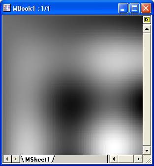
- Input data into the matrix past highlighting information technology and right-clicking. Select Gear up Matrix Values in the context menu to open the Prepare Values dialog. Blazon i*sin(ten) - j*cos(y) in the Formula edit box and click the OK push to generate information. The matrix should await similar this:
-
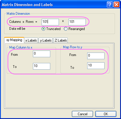
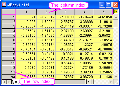
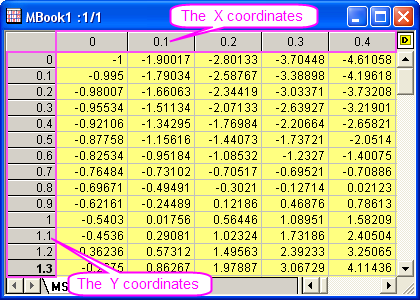
- Each data point in the matrix corresponds to two unlike kinds of indices. One is the column and row indices. The other is the X and Y coordinates. Select View: Testify X/Y from the main menu to come across the X, Y coordinates:
-
- You can also select View: Image Mode to testify the image form of the matrix:
-
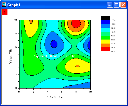
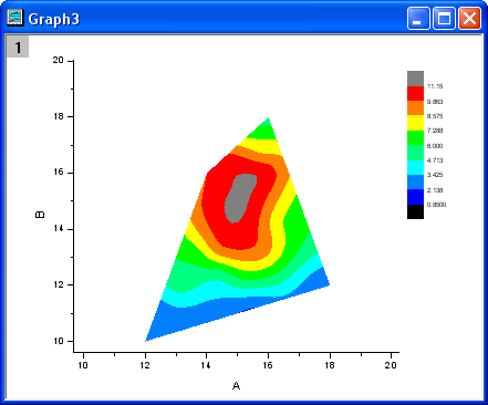
- Select View: Information Manner to exit the image mode. Create a contour plot by activating the matrix and selecting Plot > Contour: Profile - Color Fill. The graph should announced every bit shown beneath:
-
Customize Levels, Lines and Color Map
Origin makes it easy to customize every attribute of the contour plot, including the color scale and adding labels:
- Active Graph1, and select Graph: Speed Mode menu to open up the dialog. Set Speed Way = Off and click OK"'
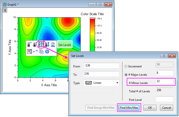
- Click on the Contour plot in Graph1, and then click on the Fix Levels button on the pop-up Mini Toolbars. In the Set Levels dialog, click the Find Min/Max button and set Major Levels to 8 and Minor Levels to 32. Click the OK push.
-
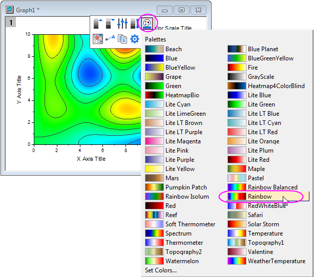
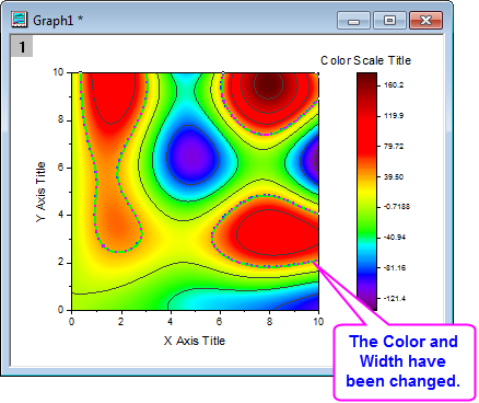
- Click on the Contour plot, and so click on the Palettes push button on the popular-upward Mini Toolbars. And so select the Rainbow palette from the drib-down.
-
- Click twice on a contour line (two split single clicks) to select all lines at that level. Modify the color to Light-green by using the Line/Border Color push
 in the Font toolbar. Change the width to three by using the Line/Border Width push
  in the aforementioned toolbar.
 -
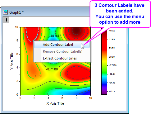
- Make sure only one contour line is selected (not all the contour lines at that level) and right click on the selected contour line. Select Add Profile Label to add a label.
-
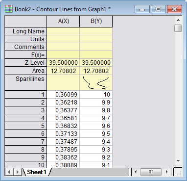
- Click twice on a contour line to select it, right click and select Excerpt Profile Lines. Origin will extract the data for that contour line to a worksheet. The following image shows part of the data in the worksheet:
-
Create a Profile Plot from XYZ Data
Origin can create profile plots directly from XYZ data in a worksheet without the need for an intermediate matrix. Delaunay Triangulation is used to compute and draw the contour lines.
- Start with an empty worksheet. Select Aid: Open Folder: Sample Binder... to open the "Samples" folder. In this folder, open the Matrix Conversion and Gridding subfolder and find the file 3D XYZ.dat. Drag-and-drib this file into the empty worksheet to import it.
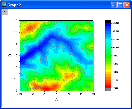
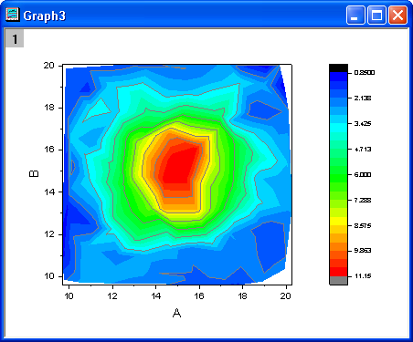
- Highlight the tertiary column and right click on it to select Set up As: Z. SelectPlot > Contour: Contour - Colour Fill to create a graph equally in the following prototype:
-
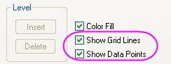
Testify the Triangulation Grid
- Show the triangulation grid that is used to create a profile plot from the data. The individual information points are located at the nodes or vertices of the grid.
- Start with an empty worksheet. Select Help: Open Folder: Sample Folder... to open up the "Samples" binder. In this folder, open the Matrix Conversion and Gridding subfolder and notice the file XYZ Random Gaussian.dat. Drag-and-drib this file into the empty worksheet to import it.
- Highlight the third column and right click on information technology to select Set As: Z. SelectPlot > Contour: Profile - Color Fill to create a graph.
-
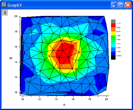
- Double click on the contour plot to open the Plot Details dialog. On the Colormap/Contours tab, click on the Line heading to open the Contour Lines dialog. Deselect Shown on Major Levels Only and select Hide All to hide all the contour lines. Click OK to close this dialog. Then select the Show Grid Lines and Show Information Points check boxes. Click OK to shut the Plot Details dialog.
-
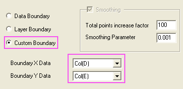
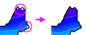
Use Custom Boundary
A custom boundary can exist practical to contour plots created directly from XYZ data where user provides the data points for the boundary in additional columns of the aforementioned worksheet. This feature is useful when there is a specific boundary data that defines the outline of an object, for case the profile of an engine where the contour shows engine temperature.
- Go along to employ the worksheet and the contour plot that was created with the XYZ Random Gaussian.dat in the previous instance.
- In the XYZRandomGaus workbook, click the Add New Columns button
 twice to add together two columns. Highlight the two columns and right click on them. Select Set Every bit: XY XY from the context menu and enter 4 rows of data such as below:
 - Double click on the profile plot to open the Plot Details dialog. Select the Contouring Info tab in the right panel. Gear up the dialog every bit in the post-obit epitome to customize the boundary for the profile plot. Remember to uncheck the Show Grid Lines and Show Data Points check boxes in the Color Map/Contours tab. Click OK to close the Plot Details dialog.
-
-
The graph should resemble the following prototype:
| | Prior to Origin 2022 SR0, the application of a custom boundary sometimes generated an imperfect fill at boundary margins. This has been improved in 2022. The user tin can restore the previous contour-make full behavior using arrangement variable @TCSM. |

Source: https://www.originlab.com/doc/Tutorials/Contour-Color-Map
Posted by: williamsalannow.blogspot.com
0 Response to "How To Draw A Contour Map"
Post a Comment